



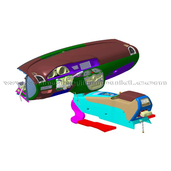
IP Moulding Tool
Automobile IP Design Instructions
1 IP Main Parts Detailed Design
1.1IP Body Structure Design
First of all, determine structure and process scheme according to modeling style and marketing position that normally IP main body injection moulding is used for the low level, by one-step making less accessories and easier process, higher productivity and lower cost. As many mounting parts are not fixed, moving parts mechanism design should be initialed before IP structure design, taking account of mechanism feature and coordination of them. Meanwhile, manufacturing process should be considered with ample analysis, for which we can do support at this part as a tool maker.
For medium-high level limousines, soft construction is used for IP including framework, foaming layer and skin. Put dashboard skin into inserts with foaming agent for moulding the framework and then fix it on dashboard cross-member and bracket. Dashboard structure design should fulfil assembly function with mounting parts and vehicle body. There are bunches of mounting parts like meters, handling units, electrical components and parts (e.g., glove box, ashtray, airbag, vent) need to be considered for their structure design, mechanism design and process analysis.
1.2Combined Meters Design
Auto meters decorate the dashboard and instantly display information and data of the vehicle. Nowadays meters including speed meter, tachometer, fuel gauge, oil gauge, coolant temperature gauge, odometer,etc. and alarm light are designed as a meter combination.
1.3Vents Design
Vents on dashboard provide fresh air in the cabin, normally they are round and square grilles, and air inlet direction can be adjusted.
2 IP Design Notices
2.1 To Determine View Distance Scientifically
IP layout scheme should be determined by view distance and plane angle. It is necessary to figure out driver’s eye positions-eye ellipse which helps to calculate and determine view range between IP and steering wheel. The max. view distance is 711mm and the best is 550mm.

2.2 To Determine Plane Angle
The angle between river’s view and IP plane should be controlled within 30°, while the angle between IP plane and plummet plane should be 10°, as the best.
2.3 To Attach Importance to IP Blind Zone and Meter Cover
After figuring out blind zone, optimize the layout of meters and display device according to blind size and position, so that the driver would read data and information quickly and correctly.
Covers would protect dust from getting inside and proper layout of position and shape effectively avoids dazzling light disturb the driver, vertical structure and inner concave shape would be fine.
2.4 Optimization of Combined Meter Cover and Buttons
As the height is confirmed, proper optimization of structure layout is to make sure it is not over boundary index requirement of the downwards view of visibility (5°), thus we can get the up boundary. For the buttons, it is great to determine layout positions by utility frequency, the more frequent, the easily hand can touch.
3 Ergonomics for IP
Ergonomics is a subject to study relations and inter-reactions between human and machines, optimizing relations among human, machines and environment as people oriented. The automotive ergonomics requirements follow GB11552(China), ECER21 and FMVSS201 which clearly explain head impact zone, immune zone and testing zone.
3.1 Head Impact Zone
According to GB11552, through a series of YZ plane tangent to IP surface we can get most forward tangent points at X direction to form a curved line named IP waterline, above which is the downward boundary of impact zone. While 100mm inside distance from glass inner surface forms the upward boundary.
As there is steering wheel which embraces airbag, driver’s head would not hit the IP. Project the area which is extended 127mm from steering wheel edges on IP to get the immune zone said by GB11552 regulation.
There are two areas defined as head impact zone for the shotgun side, one is testing zone and the other is immune zone which relates to door trim panel and pillars. Use circle in diameter of 165mm to simulate as static ball head and make consecutive adjustments under extreme status of simulation radius of 736mm and 840mm. When the round center shifts to 127mm at X direction and 19mm at Y direction, the successive intersecting of ball and IP creates curved lines formed the shotgun head impact zone. For the immune zone, as affected by door panel and A pillar the ball head can not get to the IP surface, which defines testing zone side boundary-intersect line of IP and door panel & A pillar moved inside surface by 82.5mm. Within this area, use the testing tool to hit the surface at speed of 24.1 km/h, the lasting time of that deceleration is over 80G can not be more than 3 seconds.
3.2 Interior Fittings Verification
As international regulations said area above IP waterline, the subject which head would hit should be more than 3.2mm in radius for its min. circle, and electric part buttons in the middle more than 2.5mm. If the button height is less than 9.5mm, it is required a cross sectional area of 2000mm²at position 2.5mm from top point in distance. If less than 9.5mm, 6500 mm²cross sectional area is required at position 6.5mm from top point in distance, in addition, have a power of 378N to hit the convex button, if there is no sharp edges after crack and the residual is less than 9.5mm in height, qualified.
For the area under IP waterline, mainly to check if there are sharp fittings to hurt legs, normally the thickness should not be less than 2.5mm and radius not less than 3.2mm.
3.3 Knee Protecting Area
It is under IP waterline and there should be energy absorption block inside of IP lower trim panel, in front of dummy’s knees not far than 100mm at driver side, for the shotgun side using 50% dummy not far than 125mm. While the design should leave a impact cushion space and ample activity space for the legs, using 5%, 50% and 95% dummies to do verification then get detailed data.
3.4 Packaging of the Controls
During design the first to concern is convenience for drivers to operate when doing the controls package that all switches and mechanisms related to driving should be located where the driver can reach easily. The layout contains common switches like engine hood handle, oil tank handle, control rod, hand brake, cup holder, rear mirror switch, turning switch, AC switch,etc..
We Hengji Mould just not only do IP moulding tools but also provide service for vehicle packaging.
3.5 Cup Holder Design
When do the design of cup holder, we need to consider not only the capacity but also to make sure the cup wouldn’t lean or fall out. Normally we set the cup diameter 80mm with clips to hold the cup, and the depth should not be over 70mm or it is not easy to get things out and also it can be co-used for portable drum ashtray.

3.6 Vent Design
There are two kinds of structures for AC vent to adjust air venting angle , vane type and knob type. The top air can reach driver and passenger’s eye point and the bottom to their H point.
3.7 Glove Box Validation
The opening handle of glove box is prefer to be set close to driver side with size over 45mm according to GB-10000. There are three key points for validation, shut, half open and open. The open distance should be more than 100mm and when it is completely open, it is not allowed to have interference with 95% dummy’s shank.
Hot Tags: ip moulding tool, China ip moulding tool manufacturers, makers, IP Moulding Tool, Dashboard Injection Mould, IP Plastic Mould, dashboard mould, Dashboard Moulding
Previous
IP Plastic MouldNext
No InformationYou Might Also Like


Send Inquiry