


Gas Assisted Tooling
In general, it has four stages in this process

Stage 1 – Filling by Molding Machine Injection:
Molten plastic material is injected into a mold by a molding machine to fill the part cavity. The amount of the material injected is about to fill 60~90% volume of the cavity, depending on the types of part in which how much the volume to be cored out by gas is designed.
Stage 2 – Filling by Gas Injection:
After the material filling stage has finished, gas (usually nitrogen) is injected into the center of the molten plastic material, pushing it forwards to the rest of the cavity space to fill the part cavity completely.
Stage 3 – Packing, Holding, and Cooling:
The injected gas exerts uniformly distributed pressure to the previously filled plastic material from the inside of the part outwards against the mold wall. Instead of the machine screw, here it’s the injected gas to act as the pressure source of packing and holding, while in the way that provides across the part with much more uniform pressure and a much closer and more effective pressure source. It results in much less pressure gradient and brings this process advantage over traditional injection molding, especially from viewpoints of part dimension control and avoiding part warpage. When the injected gas is exerting its packing and holding pressure, the part is under cooling simultaneously.
Stage 4 – Gas releasing:
After the part is cooled and solidified, the injected gas is released or recycled before mold opening for part ejection.
Two Types of Part in Application For Gas Assisted Molding
It is diverse to design a part in its geometry, shape, size, thickness, etc., for an injection molding process. Generally, molding parts can be categorized into two types as follows for applying gas-assisted injection molding process.
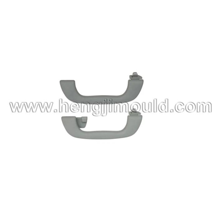
(1) Handle-like part:
So-called handle-like part refers to those such as various kinds of handles and chair arms. This type of part is so wholly thick that cycle time has to be very long for cooling if using the traditional injection molding process. It also probably brings in appearance defects such as sink marks caused by the insufficient packing effect to such a thick part. To fit in with the traditional injection molding process and eliminate the mentioned problems, this type of part is typically designed as two splitting halves, each with a regular (much thinner) nominal thickness of part surface and structure reinforced ribs beneath it. Ideally, it requires two molds and two machines to produce the two halves individually. After the two halves are injection molded, a secondary process is needed to join them, becoming a finished good.
When applying gas-assisted injection molding process at such a part, it is the gas injected to push melt forwards coring out the central portion of the part (Figure 2), then followed by the packing and holding actions pressure-exerted by the gas itself in a uniformly distributed manner from right beneath the residual thickness across the part. Compared to the original solid part design produced by the traditional injection molding process, it can result in a much shorter cycle time and meanwhile without sink mark problem. Additionally, compared to designing part with two-half components, the time and cost saved are significantly in the tooling and the finished-good manufacturing points of view. With making gas-assisted tooling, it requires only one and less complicated mold instead of two, less complex part design with less structure-reinforced ribs, and it needs only one molding machine and molding production instead of two that eliminates the need for the subsequent secondary process to join the two-half components.

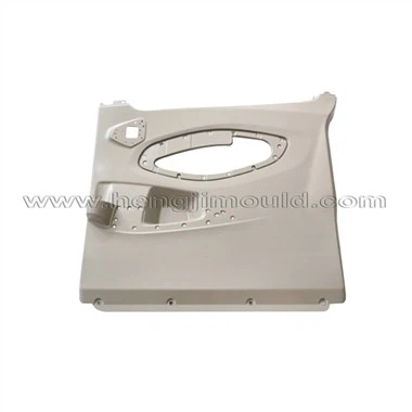
(2) Flat part:
So-called flat part refers to various kinds of table, panel, housing/cover parts in electronic devices, home appliances, automotive, etc., industries. This type of part is nominally thin in thickness in comparison with its overall length and width. The most challenging issue of producing such parts by traditional injection molding process is warpage. To overcome it, a part designer has to design structure-reinforced ribs beneath the cosmetic surface across the part to resist its trend to warp. It might require a multiple-gate design for the gas assisted tooling to provide a balanced melt filling and packing/holding effect. And hot runner system might be required to provides the part with a closer and more effective source of packing/holding pressure, etc.
When applying gas-assisted injection molding process at such a part, in lieu of the situation that central portion of the whole part is cored out as a handle-like part, gas is guided into a purposefully designed gas channel only.
.
Compared to the traditional injection molding process, the advantages it brings about include a closer and more uniform pressure source at packing and holding stages that right within the part, and fewer ribs are required to make the part equivalently strong. Both facilitate to avoid warpage problem with less cost of the mold.
Concerning a handle-like part, the part itself has acted as a gas channel already. Under proper melt gate location, gas insert location, and process conditions, the injected gas is restricted; it can flow towards one direction only within the part from one end to the other without a doubt. However not the case in a flat part; the injected gas must selectively flow along the designed route of the gas channel rather than core out the part everywhere. And if not properly design in the melt gate number/locations, gas insert number/locations, and layout of the gas channel, the gas will not necessarily flow into, along, and core out the entire length of the gas channel. In such a situation, the gas-unfilled portion of the gas channel is more like being processed under traditional injection molding process but with unusually much thicker part thickness at the base of the rib. It tends to result in serious sink mark defect at the part surface and generally is of no use in trying to solve it by adjusting parameters of process conditions. For a flat part, it is crucial that the gas channel layout is tailor-made to guide the injected gas accurately flow into/through the entire network of the gas channel; and the injected gas exists only within the gas channel without penetrating the adjacent area.
Quoted “TEN PART-DESIGN RULES FOR GAS-ASSISTED INJECTION MOLDING PROCESS” By Hank Tsai., Effinno Technologies Co., Ltd.
Hot Tags: gas assisted tooling, China gas assisted tooling manufacturers, makers, Bumper Mould Kit, co-injection, low pressure injection, molding tools, Dashboard Injection Mould, door trim mould
Previous
Gas Assisted MoldingNext
No InformationYou Might Also Like


Send Inquiry